The Yamaha XT500 was a Classic Mechanics project bike, which was broken down into at least six parts. To things manageable we've focused on the engine assembly. For full step-by-step imagery visit the image gallery.
Picture one: Last month I sorted out all the engine bits and fitted new main bearings to the crankcase. Now I'm ready to put it all back together. The XT500 uses a pressed-up roller bearing crankshaft, and it’s a pretty durable lump. It can be stripped and rebuilt with a new big end if required, but unless the bike has suffered a major lubrication failure or was showing signs of distress I'd be quite happy to simply reuse it. Our engine was running perfectly before the stripdown and there's no measurable movement at the big end, so it's going back in. With the left crankcase supported on wooden blocks the crank assembly can be driven into its main bearing with a hide hammer.
Enjoy more Classic Motorcycle Mechanics Magazine reading every month.
Click here to subscribe & save.
Picture two: I've positioned both gear shafts into their respective bearings, and engaged the selector forks on their spindles. The final component to be fitted before joining the cases is the selector drum. The drive pegs on each selector fork must engage correctly into the tracks on the drum, and a little jiggling is required to make certain everything is properly engaged. There are a couple of dowels, which fit into the crankcase half too, make sure they're present and correct before proceeding.
 Picture three: Now the cases can be joined. I've used a thin smear of Hylomar on the jointing faces and lubricated the gears and bearings with fresh engine oil before offering up the right-hand crankcase. A few gentle taps with the hide mallet are required to ensure everything is correctly engaged as the cases go together, and I keep pausing and making sure the gearbox shafts and crankshaft can turn freely. If there's any doubt at all, split the cases again to investigate as dismantling it all again later will be time consuming and frustrating.
Picture four: The crankcases are held together with a number of M6 Allen screws, all of which go in from the left side. While most of the engine castings have been powder coated I opted for a spray-on satin black finish for the crankcases, which looks quite presentable and is much easier and cheaper to do. At the bottom of the engine lies this oil strainer gauze – frequently an overlooked item – which should be removed and cleaned at each major service. I've smeared the new gasket with Hylomar before fitting the sump plate.
Picture five: With the main structure of the bottom end assembled, I've turned the engine over and am moving on to the top end next. I've cleaned up the old piston and rings, which were again in fine condition, and have lubricated the small end in the con rod before offering up the piston and sliding home the gudgeon pin. The piston needs to go on the right way round but is marked on the crown with an arrow indicating the front. As always, I've fitted one of the circlips to the piston before assembly, so only one circlip needs to be clipped in to secure the piston to the rod.
Picture six: Before fitting the barrel, this front camchain slipper blade must be bolted in. I'm using Allen screws with a drop of Locktite to make certain it's snug and secure. Then, with lots of fresh oil in the bore, the barrel can be offered up to the piston and slid home to the crankcase mouth. I've used a new paper base gasket, lubricated with a little grease, and a new rubber O-ring around the bottom of the cylinder liner. I've also carefully positioned the ring gaps at odd intervals, ideally at spacings of 270 degrees so the gaps don't line up. With the barrel bolted down and everything turning over smoothly the piston is safe from damage, and I can proceed with building the clutch side of the engine.
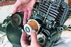
Picture seven: The oil pump is of the traditional trochoid type found in most Japanese engines, but unlike most designs Yamaha chose to incorporate the outer pump bore into the crankcase half itself. This means any serious wear would mean new crankcases, but I've yet to see an example bad enough to need such radical measures. I'm checking the rotors for any signs of heavy scoring, and priming the pump with lots of fresh engine oil before assembling it into the crankcase.
 Picture eight: Here's the oil pump sliding into place in the crankcase. It engages onto two dowels before I secure it with the three mounting screws. Note – I've temporarily removed the drive gear to allow better access to the screws. Once the pump is bolted home I can refit the drive pin and drive gear, and refit the circlip to the end of the oil pump shaft. I've also refitted the kick-starter mechanism, and slid the gearchange shaft with its selector quadrant into the casings. And don't forget the circular locating plate around the input shaft bearing, which is secured with two countersunk screws.
Picture nine: This kick-start idler gear runs on the end of the output shaft, and is again secured with a circlip. On the XT engine the kick-starter drives through this idler to a drive gear on the back of the clutch basket. The smaller DT series engines use a similar system but on those the kick-start, output and input shafts are not directly in line. This means the force of kick-starting the bike puts an upwards load on this idler, which can shear off the end of the output shaft, requiring a crankcase split to fix. Beware of DTs with freewheeling kick-starters… Note the gearchange quadrants visible below the input shaft.
Picture 10: This is the kick-start drive gear, which fits behind the clutch basket. There's a thrust washer on the input shaft, followed by a bearing sleeve. This gear then slides over the input shaft and is free to spin on the bearing sleeve. The two protruding lugs engage into recesses in the back of the clutch basket, and transmit the kick-start drive to the clutch.
Picture 11: The large captive gear on the back of the clutch basket drives the oil pump, the kick-start drive gear engages into these two machined recesses. Note the bronze centre bearing, which must be lubricated, and the shock absorber springs, which are again captive in the back of the clutch basket. As the clutch basket slides over the end of the input shaft, a little gentle rotation will allow the kick-start drive gear to drop into the two recesses. It's a big lump on the XT, but I've come across FS1E engines (which use a similar, though miniature version), where the clutch has been bolted up without the gear correctly engaged. Turn the clutch basket a few times to make sure it's properly engaged before proceeding.
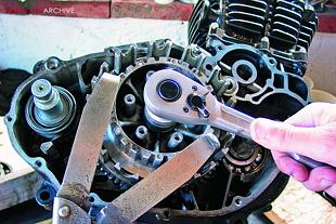 Picture 12: After the basket, there's a thrust washer and then the inner drum, which slides over the splines on the input shaft. To tighten the clutch centre nut I'm again using my favourite Kawasaki service tool, the adjustable mole-grip device with extensions that lock into the splines on the inner drum. In the absence of a similar tool or alternative, the clutch centre nut could be tightened later, after the engine has been fitted in the frame and the chain and rear brake connected up. Holding on the rear brake would provide a means of preventing the clutch rotating while the nut is securely tightened.
 ![]()