Despite the ravages of time the engine proved fairly straightforward to dismantle and I can now turn my attention to examining the internals to see what parts need attention before the rebuild. For step-by-step images of the overhaul, see the image gallery
The second part of the rebuild is subscriber only. Please see the about Classic Bikers Club page.
Enjoy more Classic Motorcycle Mechanics Magazine reading every month.
Click here to subscribe & save.
Picture one: With the cylinder head off the combustion chambers show signs of heavy carbon deposits, particularly on the left cylinder. This looks dry, rather than oily, and leads me to wonder if the bike had been running too rich. Before cleaning up the combustion chambers I’ll take a closer look at the pistons.
Picture two: The piston crowns also have heavy carbon deposits but otherwise look in fairly good shape. A few minutes work with some steel wool and Solvol Autosol reveals shiny alloy beneath. The pistons are standard, indicating that the bike has not yet been re-bored. This gives plenty of scope for reconditioning if required.
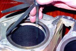 Picture three: The ring gap measurements are well within factory tolerances. I always measure the gaps at both the top and the bottom of the stroke. No wear ever occurs at the bottom of the cylinder bore so an excessive gap here gives a measure of piston ring wear.
Any wear on the bore itself will be at the top of the stroke; if the ring gap is appreciably larger here a re-bore might be necessary to recondition the bores. These simple measurements give a quick and accurate indication of both bore and ring condition.
Picture four: Satisfied that the bores and piston rings are serviceable, I can now turn my attention to the valve gear. Each valve is retained in place by two split collets engaged into the top valve spring collar.
A valve spring compressor is needed to compress each spring far enough to remove the collets, then the springs can be lifted off and the valves slid downwards out of their guides.
Picture five: Once again, evidence of heavy carbon deposits. The backs of all four valves need a good cleaning up with a rotary wire brush before proceeding. The inlet valve on the left has still to be cleaned off, the one on the right has been cleaned up. Carbon build-up like this won’t significantly affect the running of the engine but does nothing to help gas flow and should be removed while the valves are out.
Picture six: The valves need to have a good compression seal in the cylinder head. After many thousands of miles the valve sealing surface, indicated here, will begin to develop small pits as the metal suffers from constant wear and heat. Running the engine with incorrect valve clearances will also contribute to rapid valve pitting.
Picture seven: The valve seats in the cylinder head suffer in exactly the same way. With the combustion chambers cleaned up some pitting is evident in the seats. This is the area to watch carefully on older engines designed to be run on leaded fuel. Modern unleaded petrols do not have the additives required to protect these vulnerable areas and a professional unleaded conversion will include the fitting of new valve seats and new valves made from higher grade hardened steel.
 Picture eight: In my experience most Japanese engines, even quite old designs, will cope quite happily with unleaded petrol. However, the hardened steels are tough to recondition by hand and traditional valve grinding methods don’t usually make much of an impression.
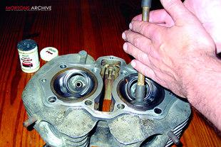
Before sending the head out for reconditioning I decide to try the traditional method of valve grinding using a wooden stick fitted with a rubber sucker. With a little grinding paste smeared on the valve seat I can then rotate the valve by hand, lapping the valve head and seat.
Picture nine: Lo and behold the traditional method works a treat, producing a splendid matt grey ring around the valve head and its matching seat. Two or three applications of grinding paste are sufficient to remove all traces of pitting and I can finish off by carefully washing the valves and seats with petrol.
However, the ease with which I lapped in these valves makes me suspicious of running this engine on unleaded fuel and I’ll be recommending that the owner uses a fuel additive like Wynns Valve Guard when running the rebuilt engine.
Picture 10: The XS650 follows a traditional sohc design and has four rocker arms held captive in the rocker cover. With the large diameter chromed plug removed, the rocker pivot pin should simply slide out and allow the rocker to pull free.
In practice, the pivot pins are quite a tight fit in the rocker cover but Yamaha have thoughtfully drilled and tapped each one so that an M6 screw can be wound in to help remove it. I found that by packing washers against the side of the casing I could progressively wind an M6 Allen screw into each pin to withdraw it.
Picture 11: The rocker arms have the valve clearance adjuster at one end and the cam follower at the other. Each follower rides over its respective cam lobe whilst the engine is running and is susceptible to wear, particularly if oil changes have been missed.
Some slight scuffing is evident here but doesn’t warrant the price of fitting a replacement. Heavy wear would mean replacement and possibly a new camshaft to boot. Check the valve clearance adjusters too, these are prone to pitting on the XS650 motor and might need to be replaced.
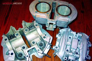 Picture 12: To remove the ravages of corrosion and years of baked-on dirt we have opted to have the head, rocker cover and barrels bead-blasted. This is a specialist job and needs to be done with care. It’s all to easy to get tiny amounts of grit into engine oilways, leading to horrors once the rebuilt engine is started up.
I entrusted the parts to Paul Coward at Bikerworld, who once again carefully masked up all the vulnerable surfaces before producing a splendid finish. The next step is to thoroughly wash the parts in paraffin and blast everything clean and dry with a compressed air jet. To make doubly sure everything's clean I then pop the bits in the dishwasher, making sure the wife is well out of the way first!
Picture 13: Before the valves go back in these valve stem seals need to be replaced. They just pop over the tops of the guides and serve to stop excess oil running down the guides which would cause the engine to smoke on the over-run. Replace them every time they are disturbed.
Picture 14: Now the valves can be re-fitted in their original positions. The valve spring compressor allows me to hold the valve springs down whilst popping the split collets into place on the valve stem. A smear of grease holds them in place while I unwind the compressor and remove it. Don’t forget the steel washers under the valve springs.
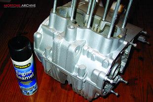 Picture 15: For purely cosmetic reasons I’ve cleaned up the crankcases and given them a coat of silver engine enamel. I’m reluctant to opt for bead blasting on such complex castings due to the risk of getting grit into the oilways. An hour spent with paraffin and steel wool before another application of the dishwasher gives a good enough surface to take the paint. Inside the top crankcase I notice the legend ‘Paul 1991’ scratched into the alloy, evidence of a previous rebuild. I’ve now scratched ‘Rod 2002’ alongside it!
Picture 16: Last month I commented that the engine can be stripped without splitting the camchain – and here’s the evidence! Unfortunately the chain does loop around the rear slipper blade mount, so will have to be split if it is being replaced. The ‘soft link’ can be easily found as the end plate is a lighter colour.
Picture 17: The front slipper blade is mounted into the barrels and retained by two M6 screws. On this engine the rubber face has become separated from the alloy blade and will have to be replaced. Apparently this is not an uncommon problem on XS650s and is worth checking at every top end strip.
Picture 18: The oil pump follows conventional Japanese design and consists of two concentric rotors running in a carefully machined housing. Unusually, the XS650 oil pump lives inside the clutch cover and the tacho drive will have to be removed first to access it. Check carefully for score marks in the housing and rotor faces. If any damage is evident the clutch case itself may have to be replaced.
Picture 19: While the tacho drive is apart check for this tiny oil seal which stops engine oil escaping and leaking out from the tacho cable. The threaded part of the cable mount screws out and the oil seal presses into the housing beneath it.
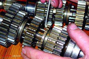 Picture 20: The gear cluster shouldn’t usually give much trouble but older XS650s can sometimes develop a fondness for jumping out of gear. Careful inspection of these dogs should reveal any problems, rounding or wear on the pins indicating a problem. I don’t normally strip gears from their shafts unless strictly necessary but if replacing a single gear cog, support the gear shaft upright in a vice and carefully remove each gear, circlip and washer before replacing in the same sequence.
Picture 21: Any gear selector problems can usually be traced to the selector forks. Watch for excessive wear or signs of blueing due to excess heat on the fork tips here. Bent selector forks will fail to engage the gears and should be replaced.
Picture 22: The kickstarter mechanism is a pretty sturdy affair and is unlikely to give problems, though this is a good time to replace the return spring if it has been showing signs of weakness. The drive gear shows signs of polishing on the teeth but this doesn’t look excessive.
Picture 23: The starter bendix gear looks to have had a rather harder life and is showing signs of wear on the edges of the teeth which engage with the crankshaft. However, looks can be deceptive; the gear teeth are actually ‘relieved’ as part of the manufacturing process to help the starter engage. Though some wear is evident I consider this gear still serviceable and we’ll be re-using it.
Picture 24: The old sump filter proved to have a piece of gauze missing. Not only was this not filtering the oil as it should, it also makes me wonder what happened to the missing piece! However, as no signs of foreign bodies were evident in the engine I’ll simply replace it with a new one (left).
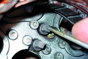 Picture 25: Final thing to check before the rebuild are these two carbon brushes which fit onto the alternator stator and bear against two copper tracks on the rotor. Excessive wear on these brushes is a common cause of charging problems on these bikes and is easy to overlook. These are about half worn, and should be good for a lot more miles.
And that’s all the bits sorted out. The engine has proved to be in better condition that we’d expected and I’m wondering if the owner’s original problem was down to a carburation fault as evidenced by the excessive carbon deposits in the top end.
Reconditioning the valves should help it to run better and we’ve decided to replace the camchain as a precaution while it’s being rebuilt.
In part two, I’ll be clearing the workbench and bolting it all back together. ![]()