In part one I started work on Chris’s Triumph Trident engine which had come to me in a row of cardboard boxes after being stripped by a previous owner in the distant past. Though the major engine parts had already been reconditioned, assembling the pile of bits back into a functioning engine proved to be quite a task and I had begun to think of the T150 as the most complicated motorcycle engine ever. Having managed to assemble the major engine components it’s now time to explore the intricacies of the Trident’s unique transmission and clutch.
The Trident is certainly more of a challenge to work on than any conventional Japanese four cylinder engine and buries the myth for ever that old British bikes were simpler and easier to work on than their foreign counterparts. It must have been hugely labour intensive to build at the factory, and in some ways represents a last bastion of British craftsmanship in the face of an influx of foreign designs more suited to mass production. But it’s been a hugely satisfying project to work on, and I’m looking forward to seeing Chris’s bike finally back on the road again.
Enjoy more Classic Motorcycle Mechanics Magazine reading every month.
Click here to subscribe & save.
For step-by-step images and captions, click on the image gallery.
Captions
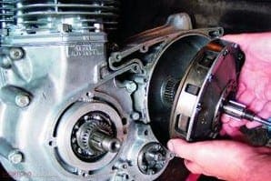
 Picture 1: Before delving into the gearbox I want to finish off the timing side of the engine and fit the outer cover, so I’m starting out by refitting the alternator rotor back onto the right hand crank end. This is located with a Woodruff key which was missing from the pile of bits. Note the timing marks on the rotor face, unique to the Trident. The other side of the rotor has the timing marks for the twin cylinder engines.
Picture 2: Before refitting the alternator stator I’ve popped a new circlip and washer on the intermediate timing wheel shaft. These tiny but vital parts were missing too, and also came from Norman Hyde. The alternator wiring threads upwards through the back of the timing case, passing though a new rubber grommet which proved difficult to source.
Picture 3: Gearbox mainshaft third and fourth gears look to have suffered from heavy corrosion, probably from being stored somewhere in damp conditions. This pitting to the case-hardened gear teeth renders them unusable. Fortunately specialist Nige Bamber comes to the rescue with a pair of good secondhand gears.
Picture 4: The high gear has two needle roller bearings fitted to support the mainshaft, and this oil seal is essential to stop gearbox oil leaking past the bearings. The high gear itself runs in a specially made bearing fitted to the back of the gearbox shell. The bearing rollers run direct on the machined surface of the high gear, so replacing the bearing means also replacing the complete high gear assembly.
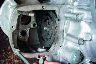 Picture 5: Before assembling the gear shafts I’m fitting the camplate to the inside of the gearbox shell. This detent plunger and spring screws in from underneath to ‘click’ the gears into position. I’m setting the camplate to the third gear position (shown) before fitting the gearbox shafts. Note the high gear bearing, just visible at the back of the gearbox shell, and the new needle roller bearing for the layshaft below it.
Picture 6: With the high gear in place in its bearing and a new thrust washer fitted to the layshaft needle roller I can now engage the two gearbox shafts and gently slide them home. With my right hand I’m holding the three selector forks in place on their respective gears. The gearbox layout owes its origins to Edward Turner’s original four speed pre-unit design so space is tight for the five speed cluster and some patience is required to get everything correctly located.
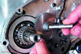
Picture 7: With both gearbox shafts engaged in their respective bearings and all three selector fork rollers correctly engaged with their tracks in the camplate, this shaft slides through the selector forks and engages into the back of the gearbox shell to finally hold everything together. Earlier Tridents had a four speed box, which was slightly easier to work on. The designation “V” at the end of the model number (as in “T150V”) designates the five speed box option, and was standard from 1971 onwards.
Picture 8: Next, the gearbox inner cover goes on. I’ve fitted a new ball bearing to support the mainshaft and a new needle roller for the layshaft. Here I’m fitting another new thrust washer onto the layshaft bearing. A smear of grease will hold it in place while I assemble the gearbox. Note the gearchange quadrant which pivots in the cover. The teeth on the quadrant rotate the camplate to select the gears and the quadrant must be indexed to the camplate as the cover is fitted.
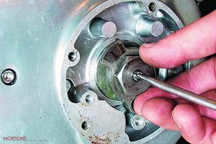
Picture 9: With a smear of silicone sealant applied to the rear mating surface I can now slide the gearbox inner cover onto the gearbox shafts, pausing just before it meets up to the crankcase to index the quadrant to the camplate. A straight edge lined up to the centre of the mainshaft and gearchange shaft housing (shown) should line up to the centre of the second tooth on the quadrant. If the quadrant isn’t indexed correctly there will be problems finding top or bottom gears.
 Picture 10: When I’m satisfied all the gears are selecting properly I can fit the kickstarter pinion and spring over the end of the mainshaft. Kickstarter pinions can wear heavily on these engines but this one looks in surprisingly good condition. The return spring behind the pinion was broken though and again I’ve had to ask Norman Hyde to pop a new one in the post before completing the gearbox build.
Picture 11: Now the kickstarter ratchet mechanism fits over the pinion and the end nut goes on to the mainshaft with a new locktab. The pinion must be free to move back and forth. If it sticks in the inboard position the kickstarter will meet no resistance when operated, which has led to some unpleasant cracks to owners knee joints when they’ve leapt on a kickstart lever which has banged straight down to its stop. Ouch.
Picture 12: Before fitting the gearbox outer cover I’m stripping and checking the gearchange positive stop mechanism. These two plungers ride up past their catch plate to hook into the teeth on the quadrant when the gear lever is operated, and they must slide freely in their housings. Condensation inside the gearbox sometimes results in rust on these plungers, but these look fine, and I’ve greased them before reassembling the catch plate.
Picture 13: Also in the gearbox outer cover is the kickstarter quadrant and return spring. This is sturdy piece of kit and rarely gives trouble, though the return springs can occasionally break. I’ve fitted a new oil seal and housing into the cover before fitting the quadrant to the cover.
Picture 14: After applying a smear of silicone sealant to the back of the cover I can now slide it into place over the two studs in the crankcase and bolt it home. The kickstarter spring needs to be under tension as the cover goes on to allow the quadrant to clear the kickstart pinion. In the absence of a kickstart lever I’m using Mole Grips on the kickstart shaft to tension the spring as I fit the cover.
 Picture 15: At the other side of the gearbox now, this oil seal and housing fits around the high gear with three small Allen screws. The oil seal runs on a ground boss on the back of the gearbox sprocket to prevent oil leaking from the gearbox.
Picture 16: To retain the gearbox sprocket this large nut winds on to the high gear and is locked in place with a new locktab. Note the O ring (which actually fits behind the locktab, not over it as shown), there as an additional measure to prevent loss of gearbox oil.
Picture 17: At the design stage the Trident engine required a completely new transmission approach to the old twins, which had always featured wet, multi-plate clutches and duplex primary chains. Working with Borg & Beck, Triumph specified a single plate, dry clutch and chose to run it inboard of a conventional wet duplex primary set-up. This housing at the engines drive side provides a home for the clutch.
Picture 18: The component parts of the clutch, stripped, cleaned and laid out for inspection. Clockwise from bottom, the rear housing, outer pressure plate, diaphragm spring, front housing, clutch plate and clutch hub. In the middle is the clutch pull rod. These clutches are sturdy units and will take loads of abuse but while it’s apart it’s wise to check the clutch for wear. A phone call to Norman Hyde brings the response “change it when it’s worn down to the rivets”.
Picture 19: The clutch hub is located with another Woodruff key, and then bolts on to its taper on the gearbox mainshaft. Then the whole clutch assembly simply slides on to the hub as a unit. Dead easy. It’s important to remember the clutch pull rod which must pass through the clutch assembly from the rear. Miss this out now and you may have to strip all the primary drive assembly later to fit it.
 Picture 20: With the clutch assembly in place the inner primary cover now bolts up to the drive side crankcase and closes the clutch housing. Before fitting the primary drive I’m assembling the oil pump drive gears. The crank drive gear fits on to the crank splines, the drive gear on the pump is secured onto the pump’s drive shaft with a single nut and locktab, and this idler wheel fits onto its own shaft to transmit the drive. Watch for the oil hole in this shaft, if it goes in the wrong way round the bush in the idler wheel could run dry.
Picture 21: The primary drive sprocket has a built in shock absorber comprising a central splined spider sandwiched between vanes in the outer drum. The workshop manual describes a special tool for compressing the rubber blocks to aid assembly, but I find they fit in fairly easily with just a spray of duck oil to help. Then the face plate goes back on with a new set of bolts and locktabs.
Picture 22: Now the primary drive fits on as an assembly, the crank sprocket fitting over its splines while the primary sprocket/shock absorber fits onto the splined shaft on the end of the clutch housing. As the primary chain is endless these parts must be fitted together. If building an engine from scratch it’s important to assemble everything temporarily first before shimming the engine sprocket to ensure the primary chain has a straight run.
Picture 23: Primary chain tension is adjusted by this pivoting slipper blade in the outer cover. The original was badly worn and it’s taken quite a hunt to track down a new one. New triplex primary chains are getting difficult to find and the duplex chain fitted to the later T160 is almost unobtainable now, so many Trident owners are turning to aftermarket belt drive conversions to keep their bikes running.
 Picture 24: Finally the outer primary cover goes on, and it only remains to fit and adjust the clutch lifter mechanism, a fairly conventional ramp and ball device. The pullrod adjuster needs turning until it contacts the clutch, then backing off half a turn before locking up with the locknut.
 ![]()