When Suzuki launched their first four-stroke back in the early Seventies they had gone to some trouble to get the design right. Environmental legislation was beginning to signal the end for high performance, smoky two-strokes, and with the GS750 Suzuki laid the solid foundation for their four-stroke GS range that would later produce variants from 550 to 1000cc, and later mature into the 16 valve GSX series.
Pundits of the time noticed a certain similarity to Kawasaki’s Z1 from which the GS undoubtedly drew inspiration, and like the Z1 the GS has proved to be a solid and reliable engine capable of covering huge mileages without complaint.
Enjoy more Classic Motorcycle Mechanics Magazine reading every month.
Click here to subscribe & save.
When Jason dropped his engine off to me for a rebuild he told me how he’d had his trusty GS750 on the road for over ten years and it had never missed a beat, though it now occasionally jumped out of second gear and was beginning to use a little oil.
For step-by step photos and captions, visit the image gallery.
Captions
Picture one: The GS750 is a big lump but is very well engineered. The design helped establish the “universal Japanese motorcycle” (UJM) layout of the late Seventies with two overhead camshafts driven by a central camchain. The crank runs in roller bearings with direct gear drive to the clutch and unit construction gearbox. The generator and starter clutch are mounted on the left hand end of the crank, with the points ignition mounted on the right. Jason’s engine looks a bit tatty, but seems basically sound with no obvious seized bolts or broken cylinder fins.
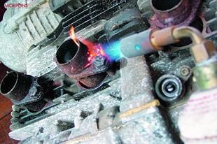
Picture two: However, at some point in its previous history the bike has been run with an unknown aftermarket exhaust, the remnants of which have been hacksawed off and left to rust into the cylinder head. First challenge, then, is to try and get these rusted bolts free. Despite several days soaking in Plus Gas and as much heat as I dare apply only one bolt can be persuaded to unscrew, the rest stubbornly stay put and shear off their heads. For the time being the sheared bolts can stay in the head and I’ll seek specialist attention later.
Picture three: To begin dismantling the engine I’m starting with the generator side. The casing screws come away without drama and I can pull the cover off the crankcase revealing the stator captive in the outer cover, the rotor and starter clutch assembly, and the reduction gears for the starter motor drive.
Picture four: The starter reduction gear sits on its own shaft, sandwiched between the crankcase and generator cover. With the cover removed it simply slides out and the gear comes free. Watch out for the two thrust washers fitted either side of the gear.
Picture five: It’s possible to strip the engine right down and leave the generator rotor in place on the crank, but it has to be removed to gain access to the starter clutch behind it so I’ve opted to remove it now. The rotor fits on a taper on the crank end, and is likely to be a tight fit. This is the genuine Suzuki workshop tool for removing it. With the centre bolt removed the slide hammer screws into the extraction thread in the rotor, and a few sharp whacks frees it off the crankshaft without damaging the delicate magnets in the rotor edge.
Picture six: The starter clutch housing is secured to the back of the rotor with three countersunk Allen screws. The starter drive gear is free to spin on the crankshaft supported by two bronze bushes. There’s no need to remove the starter housing from the rotor unless it needs replacing. Watch you don’t lose the three small rollers, pins and springs from the housing as it comes away. I always refit the drive gear into the housing and store it away as an assembly at this stage.
 Picture seven: On the right side of the engine I’ve now removed the points cover to reveal the heart of the ignition system. Like most early Japanese fours the GS750 had two sets of points, one set for cylinders 1 & 4, and one set for cylinders 2 & 3. The points are mounted on a common backplate and can be adjusted independently of each other to facilitate accurate ignition timing. This is reasonably easy to set up from scratch during the rebuild, but to give me a reference to work from I’ve scribed a mark here to indicate the location of the backplate before removing it. Then removing three M5 screws allows me to lift the whole thing away as an assembly.
Picture eight: Behind the points backplate is the auto advance unit. This features a central cam which opens and closes the points as the crank rotates. The cam is mounted on its own backplate and is keyed to it by two small bobweights and springs, allowing centrifugal force to vary the ignition timing and tailoring it to the requirements of the engine as it runs. The whole assembly fits onto the crank end with a single bolt, and is located with a small pin captive in the crank. With it removed you can now see the oil seal on the crankshaft, but the cases have to be split to change it if it’s leaking.
Picture nine: Rearwards of the points is the clutch housing. Again the cover comes away easily, and I can immediately begin to strip the clutch by undoing the six bolts which keep the clutch springs under tension and retain the outer plate. Note the kickstarter toward the rear of the clutch – later GS models dispensed with the kickstart and used a different clutch outer cover without a drilling, but the mountings in the crankcase remained throughout the bike’s production run.
Picture 10: With the clutch springs removed the pressure plate lifts away, and I can slide the clutch plates out from inside the basket. I did notice the clutch springs looked slightly different to the usual GS items, and these friction plates have linings in an unusual brown colour. It looks like a previous owner has fitted a high performance clutch kit to this engine, a fairly common mod as it’s as easy to fit high performance parts as standard ones when the clutch needs replacing.
Picture 11: The clutch inner drum is retained onto the end of the gearbox input shaft with a single hexagon nut, and can be removed without drama once the nut is unscrewed. The clutch basket spins on the input shaft, and on the GS engines is mounted on needle roller bearings on a large diameter steel boss. The purpose of this boss becomes clear when you need to remove the clutch basket; as the GS engines have direct gear drive from the crankshaft to the clutch basket, removal of the boss allows the basket to be pulled backwards and out of mesh with the crank. It can then be lifted free. To make life easy Suzuki have drilled and tapped two M6 threads into the boss, and here I’m using one of the outer cover screws to pull it clear.
 Picture 12: With the clutch removed I can now lift the oil pump drive gear away. This gear also spins on a needle roller bearing on the input shaft, and is driven by two lugs on its forward face which engage with two slots on the back of the clutch basket. For racing or high performance purposes it’s possible to replace the oil pump gears with a set offering a different ratio, which in turn flows oil around the engine faster. However these will not increase the oil pressure and will not compensate for a worn or damaged oil pump.
Picture 13: The gear selector mechanism differs from conventional Japanese design and uses a spring-loaded pawl system to rotate the selector drum. As with many other designs, though, the gearchange shaft passes right through the engine. A circlip retains it at the other end, and once I’ve dug through the old chain grease and muck to locate and remove the circlip the shaft pulls free from the right hand side. This is the part you’d be replacing if you found badly worn splines on the gearchange shaft, not unknown on Suzuki engines.
Picture 14: Next I’ve removed the three screws securing the oil pump to the lower crankcase and here I’m lifting it clear. I’ll be taking a good look at the oil pump later – on the GS design the oil pump is in the lubrication path before the filter, which means it can pick up detritus from the sump and suffer from internal scoring. The GS roller bearing engines are designed to run at fairly low oil pressure, so even light scoring on the pump internals can significantly reduce oil pressure across the engine. Finally note the retaining plate around the input shaft and the blanking plate to the rear of it. Both of these span the crankcase halves and have to be removed so the cases can be spilt later.
Picture 15: Turning now to the top end of the engine, removing the cam cover reveals the two camshafts and their single row chain. Before removing anything I always take the precaution of sketching out the valve timing marks. Here I’ve positioned the engine at 1&4 top dead centre. Note the arrow marked 1 on the exhaust cam which now aligns with the cylinder head flange, and I’ve counted back from there to note the 27th pin on the camchain lines up to the arrow marked 3 on the inlet camwheel. This information is undoubtedly in the workshop manual but it’s a good habit to get into, particularly when working on an unfamiliar engine.
Picture 16: Now, with the engine still at 1&4 TDC, I can unbolt and remove the camchain tensioner from the rear of the cylinder block. Locking the tensioner up with its pinch bolt first allows me to measure how far the plunger has extended in service once I have the tensioner on the bench, a useful technique to assess the degree of camchain wear. In this case it’s academic, as Jason has wisely opted to have a new camchain fitted while the engine is stripped down.
 Picture 17: I’ve unbolted the top centre camchain idler roller from the head and lifted it clear before gently undoing the cam cap bolts in sequence to release the exhaust camshaft. Even with the engine correctly positioned at 1&4 TDC the valves on cylinders 2&3 will be partially open and will push the camshaft upward under valve spring pressure as the cap bolts are released. Unscrewing the cap bolts in sequence stops the camshaft lifting at too extreme an angle and getting wedged in place.
Picture 18: Just like the early 900 and 1000 Kawasakis, the GS series engines used bucket and shim type cam followers with the shims pressed into the tops of the buckets. I’ll undoubtedly be doing some reconditioning work on the valves and will probably have to re-shim the engine from scratch when I rebuild it, but even so I always make a note of what shims were fitted in which position when the engine was stripped, another good habit to get into in the workshop. The shims can be popped out of the buckets with a small screwdriver, and have a size etched onto one side as you can see here. If you’re lucky the shims will have been fitted with the sizes on the lower face, if fitted the other way up the action of the cam lobes will have polished the size markings off the shims. When shimming a bike on the bench this means you often have to resort to a micrometer to establish existing shim sizes.
Picture 19: Before the cylinder head comes off the front camchain slipper blade lifts upwards out off the top of the cylinder barrel. These are remarkably sturdy on the GS motors, and don’t always need to be replaced each time the engine receives a new camchain. Now I can undo the cylinder head bolts in sequence and lift away the head.
Picture 20: Now for the tricky bit. The design of these bikes means that road spray from the front wheel will have been directed straight at the front cylinder studs. Take a mixture of steel studs and alloy castings, repeatedly soak in salt water and then leave to corrode for 25 years and it’s almost inevitable that the barrel will need some persuasion to come free from the crankcase mouth. On one occasion I worked on a GS750 which was so solidly stuck together I had to decide whether to sacrifice the barrels or the crankcases as butchery became inevitable. The crankcases won, and I cut the barrels off in big lumps with a grinder and hacksaw. I hate doing this, particularly as parts are getting scarcer. On Jason’s engine I’m hugely relieved when the barrels start to move after only relatively gentle persuasion.
Picture 21: It still needs a mixture of care, time and applied brute force to get the barrels clear of the cylinder studs without damaging either the gasket faces or the pistons and rings. The resulting cascade of rust inevitably drops into the crankcases, not a problem in this case as I’m completely stripping the engine and will be cleaning it all up later. Getting the barrels off without causing terminal damage with the engine in the frame is not something I’d like to try. Now I can remove the rear camchain slipper blade, bolted into the crankcase mouth with a single M8 bolt.
 Picture 22: The pistons are easy enough to remove after that little saga. With the outer circlips removed the gudgeon pins slide out of the small ends and the pistons lift clear. I always mark the pistons inside the skirts so I know which cylinder they came from, as I may be re-using them later on. Incidentally it’s not necessary to remove both circlips from each piston, leaving one circlip in each makes re-assembly easier and saves having to buy eight replacement circlips.
Picture 23: Almost ready to split the cases now. Turning the engine upside down I can remove the sump plate to get at the two main crankcase bolts within. The oil pump strainer looks reassuringly clean but there’s a fair old amount of sludge built up in the sump itself, usually a sign of missed oil changes. Though it’s not a scheduled maintenance item I always like to drop the sump off my bikes each year or so to keep it clean inside and check the strainer gauze is clear. It’s easy enough to do when changing the oil and only costs the price of a new sump gasket.
Picture 24: After removing all the crankcase half bolts the lower crankcase lifts away to reveal the crank and gear shafts in the top half. The gear selector drum and forks remain in the lower crankcase half at this stage, and I’ll remove them later for inspection. The two gear shafts lift away and get put to one side too. Note the thin half circular clips in the crankcase, there to engage with the grooves in the gear shaft bearings. These can come loose when lifting the shafts out and are easily lost.
Picture 25: And finally the crankshaft lifts out of the top crankcase half. The GS has a roller bearing crank and can be treated as an assembly, only requiring specialist attention if the bearings have shown signs of distress. That means the con rods will stay on the crank, and there are no bearing shells to replace. Note the camchain hooked around the crank too, if you are fitting a new camchain to one of these engines you have to strip it down as far as this to hook the new endless chain in place, one reason why many owners opted to have soft link camchains fitted instead. That’s also why I’d always fit a new camchain while the engine is dismantled, having got this far it seems like false economy not to. ![]()