I had already stripped Steve’s Kawasaki 400 twin engine into its component parts and now it’s time to take a good look around the bits to see what needs to be replaced for the rebuild.
Ringing Z-Power for some advice about gaskets and parts availability gave me something of a surprise, as they told me the engine number I’d quoted was for an old Z400 twin rather than a 440. Rather belatedly I scrubbed the old grease from the front of the cylinder barrel to reveal the capacity cast on by the manufacturer – 396cc!
Enjoy more Classic Motorcycle Mechanics Magazine reading every month.
Click here to subscribe & save.
A good job I discovered that before ordering any parts as there are many minor but important differences between Kawasaki’s early Z400 twin and the later 440 development.
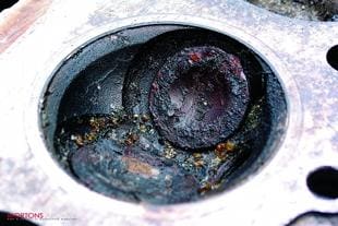
Picture one: I was hoping to avoid running up too much of a bill for Steve but the state of the left hand cylinder bore suggested that he was going to have to spend some money. The engine had been left with its plugs out, moisture had penetrated the cylinder and the rings had rusted badly into the bore itself. Enquiries indicated that new, genuine pistons would be expensive so I rang Steve who immediately set about hunting down some serviceable second hand barrels, or at least some good oversize pistons we could use for a re-bore.
Picture two: Corrosion had also begun to affect the valves, though when I removed them from the head and cleaned them up with a rotary wire brush I was pleased to see that they were still going to be usable. However, the valve seats were very badly pitted and some specialist work was obviously going to be required. I took the head and valves off to Paul Coward at Bikerworld to see what could be done.
Picture three: Paul took a good look at the valve seats before deciding that they were beyond simply lapping-in with grinding paste and would have to be re-cut. This is quite a skilled operation and requires special tools. Fortunately Paul had just received a new set of valve seat re-cutting tools from Sykes-Pickavant, and was keen to try them out on the little Kawasaki’s cylinder head. The set comprises a selection of cutting heads to suit the range of valve head diameters found on common bike engines, along with an assortment of pilot bars which have to fit accurately into the valve guide to locate the cutting head.
Picture four: The first step in the cutting operation is to mark around the valve seat with engineers blue. This will make it easy to see the pits on the valve seat when the cutting operation starts.
Picture five: This is the cutting head itself. Cutting heads are available for different angles of valve seat, this one cuts at 45 degrees which is the usual angle for most road bikes. However on racing engines, or where some gas flow work has been carried out on the head, the seats will frequently be cut at three different angles to produce a nice, narrow sealing face and provide a smoother radius to aid gas flow. Paul explained just enough gas flow theory to me to convince me that this was highly specialist stuff, and best left to an expert like him.
Picture six: With the correct size pilot bar mounted into the valve guide, the cutting head slides into place and Paul gently turns it against the seat to skim off a little metal. The skill is to take off just enough metal to remove the pitting without cutting too deep. If the seats are overcut the valves will sit too deep in the head, a condition known as ‘pocketing’. Taking off too much metal can also make the valve seats too wide.
 Picture seven: After skimming a little of the seat, Paul removes the cutter to check progress. You can clearly see the new metal beginning to show at the top left.
Picture eight: Of course, with seats as bad as these it’s inevitable that the valves will have suffered too. Close examination shows how the valves have worn into ridges which will need to be carefully skimmed off in a lathe before they can be lapped in correctly to the re-cut seats. All this removal of metal will affect how deep the valves sit into the head on re-assembly. And be very careful if undertaking this kind of work on dohc engines as you can inadvertently go beyond the range of available shims for the valve clearances. This could make valve replacement the best option in some cases but our Z400 uses screw and locknut tappet adjusters and shouldn’t prove troublesome to set up later.
Picture nine: After some time and care Paul has successfully re-cut and lapped in all the valves and seats. Thank goodness this engine has only four valves – the thought of carrying out a similar process on a Honda CBX1000 isn’t a pleasant one!
Picture 10: Finally I can re-fit the valves back into the cylinder head, having first fitted a new set of oil seals over the guides. As usual, my old valve spring compressor proves invaluable. With the spring compressed I can pop the split cotters back onto each valve stem to hold everything in place. A blob of grease on the stem stops them falling out while I unwind the compressor.
Picture 11: Turning to the rest of the engine I’ve carefully checked the bearing journals on the camshaft before using a micrometer to check the journals for wear. It’s worth measuring at several places around each journal as this will reveal any ovality, but problems with the cam bearings will usually be pretty obvious with scoring present on the camshaft and cylinder head.
 Picture 12: Similar measurements will reveal any wear on the big end and main bearing journals, and close visual inspection will show up any scoring here. The Kawasaki uses plain bearings as opposed to rollers, which means that some re-conditioning can theoretically be carried out if the journals have sustained any damage. However, re-grinding is not usually an option as Kawasaki do not supply oversize shell bearings and specialist attention would be required to build up worn journals and re-grind them back to standard. It’s also worth checking the balancer chain drive teeth in the crank centre – early Z400s could strip teeth from here and render the balancer unserviceable, making the bike unrideable.
Picture 13: The main bearing shells themselves are a press fit into the crankcase half and can be popped out with a small screwdriver. Although Kawasaki do not supply oversize shells they do offer three ‘standard’ sizes which are graded to match the journal. These grades are sometimes identified by coloured spots of paint, which can lead to some confusion when ordering replacements. The factory manual has a chart to help identify the correct shells once the dimensions are known. If in doubt a specialist like Z-Power can offer help over the phone.
Picture 14: As I’d hoped, the journals all seem fine in this case but the shells themselves are showing their age. The old shell (right) shows clear signs of pitting compared to the new one (left). This will be worse on an engine which has not received regular oil changes throughout its life. In any case, I’d always replace both big-end and main bearing shells as part of a full engine rebuild as a matter of course.
Picture 15: The big-end shells pop out of the con rods in exactly the same way and their replacements can be eased home by hand. It’s most important that the con rod caps go back on the correct rods and that each rod goes back on the correct journal. If in doubt I always label the rods and caps with a marker pen before disassembly, but the manufacturer should have already marked them at the factory.
Picture 16: It is not actually necessary to remove the generator rotor from one of these engines in order to split the crankcases but before I rebuild the engine I want to make sure the starter motor clutch is in good working order. As this is mounted behind the rotor I’ll have to remove it now. With the crank carefully held between thick rags in my bench vice I can remove the centre bolt and use this useful Honda puller to pull the rotor from its taper. Remember, though, that due to the Z400’s ‘reversed’ crank rotation, the centre bolt has a left handed thread.
 Picture 17: Now I can simply lift the starter drive wheel out of the starter clutch housing. The drive boss (indicated) can begin to develop flats after high mileages which can cause the starter clutch to slip under load. This one does show signs of wear but as Steve’s budget is beginning to feel strained we opt to leave it. The bike does have a kickstarter after all! Note the three Allen head screws which hold the starter clutch on to the back of the rotor. The old Z750 twin was notorious for writing off rotors when these screws would work loose in service. If in doubt, slot the threaded end of each bolt with a hacksaw and then spread it out to lock it into its thread after re-tightening. Use plenty of Loctite too.
Picture 18: The Z400 has a primary chain, a camchain and a balancer chain. Rather too many internal chains for my liking and none of them cheap to replace. The primary chain in particular is hideously expensive but fortunately also fairly sturdy. Careful measurement of a length of the camchain here confirms my preference to fit a new one and the balancer chain is right on the service limit too.
Picture 19: Fitting a new balancer chain involves removing the two bobweights from their mountings and looping the chain around them. I’ve also taken the precaution of replacing the rubber faced slipper blade mounted up inside the housing.
Picture 20: The usual routine checks for wear or damage show no signs of any problems with the gears and shafts and the sliding dogs look perfectly fine too. Always worth checking while the engine’s apart though.
Picture 21: Again I check the selector forks for any signs of wear or damage. Bent selector forks will frequently show signs of heat discolouration as well as signs of scuffing on the tips, here.
 Picture 22: Still on the transmission, don’t forget to check the rear of the clutch basket for any broken springs in the shock absorber. This small drive gear is for the oil pump and, unusually, is retained with a circlip.
Picture 23: The clutch plates should also be checked for wear. These are about half worn, so to keep costs down I’ll be re-using them. I’ve also checked each of the plain plates for any signs of buckling by laying it on a piece of plate glass from an old record turntable. Unless they are perfectly flat the clutch will be difficult to adjust and could exhibit symptoms of both slip and drag.
Picture 24: Hmm, I don’t like the look of this. Something has obviously gone around inside the oil pump at some stage and scored the faceplate. This could reduce the running oil pressure and, mindful of the new bearing shells I’m fitting to the engine, I’ll be looking for a better condition second-hand pump to fit on the rebuild.
Picture 25: Finally, to make the rebuilt engine look as presentable as it deserves, I’ve opted to give the crankcases a coat of high-temp satin black paint after thorough degreasing and cleaning in the dishwasher.
Not original I know, but as the engine is to be used for a project it doesn’t have to look as it did when it left the factory. Half an hour with some Solvol Autosol on the engine covers and a set of stainless screws and it should look quite presentable.
Unfortunately, another phone call to Steve reveals that good replacement pistons are proving elusive and we’re hoping something turns up in time to get the motor rebuilt next month. Otherwise it could be an exercise in breaking the bank! Let’s hope not… ![]()