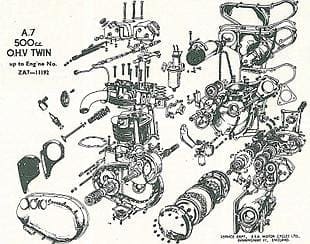
BSA's 500cc parallel twin, the A7, was introduced in September 1946, though the initial design was laid down before 1939. It was a bit of a 'committee' engine — the basic layout is attributed to Val Page, Edward Turner laid hands on it during his time at BSA during the war and Bert Hopwood oversaw its developments after the war.
Dimensions of 62mm bore by 82mm stroke gave a swept volume of 495cc and this version of the engine lasted until 1950. The basic principles are the same on early and late A7s, though not many parts are interchangeable between the two versions. The first engine had a bolted on gearbox, with slipper tensioned primary chain. At the top end of the engine one of the most noticeable differences was the four hexagon headed rocker caps, while in the drive line, the clutch ran dry.
Enjoy more Classic Motorcycle Mechanics Magazine reading every month.
Click here to subscribe & save.
Bigger model
In 1950 the 650cc A10 was announced. The motor had been slightly redesigned, and the bigger model had dimensions of 70 x 84mm. The A7 was revised to 66 x 72.6mm. One of the major innovations lay in the cylinder head and rocker boxes, with the head incorporating the induction manifold and the box now a one piece item with two covers. The tappets had been revised, as had camshaft oiling arrangements, and the crankshaft, though of the same basic design, now ran in a roller bearing instead of a ball race. The plain bush on the timing side remained. In this form the engine continued in production up until 1963, when the last of the A10 variants was made and the unit construction A65 and A50 range was adopted.
Many BSA owners prefer the pre-unit engine twins to the later unit construction A50/65 models, although the latter are much simpler to work on, especially as regards fitment of the cylinder head and rocker box. However, with patience, practice and care no real problems are encountered for the average 'do-it-yourself' owner who likes to do his/her own engine overhauls. Obviously, major jobs. like crankshaft regrinds and rebores have to be, or are best, left to the specialists, but most jobs like valve, valve guide, piston and big-end replacements can be done at home in the small workshop or shed.
Cleanliness is essential and each part upon removal should be cleaned and free from dirt or rust Before commencing the overhaul it is ideal to have the following items to hand, as well as a gasket set and new parts which are known to be in need of replacement: cleaning material (paraffin), soft cloths, fine emery cloth, jointing compound, grinding paste, grease, engine oil, set of piston ring circlips, feeler gauges, BSF/Whitworth spanners and hide mallet, and if possible a pushrod comb (tool '76-9114), a boon for fitting one piece rocker boxes.
Some pattern parts on the market do prove to be inferior to the original and unfortunately dealers like us who sell them and use them in renovations have no idea of the quality until a failure occurs. I feel it is about time some of the manufacturers stopped conning the consumer with shoddy items and manufactured parts of the correct quality material. However, I digress.
Poor oil consumption and lack of compression is more likely to be due to worn valve guides, worn or burnt valves and weak valve springs than worn piston rings. However, excessive piston ring slap, when the engine is warm may indicate worn cylinder bores which can be checked when the cylinder head is removed. Vibration could be the fault of loose front engine-steady stays or lack of them. We have come across several machines where these important items have been discarded
 Drain all the oil from the engine unit before commencement of dismantling. Most people can dismantle an engine unit, so we won't go into too much detail with this operation, though it is important to remember that excessive force should never be used, and parts should be clearly labelled or stored in marked boxes. What seems easy to remember at the time becomes a jumble of disparate nuts, bolts, screws and unidentifiable lumps. Rebuilding an engine correctly is another matter.
Removal of the rocker box involves four bolts (which also hold the head steady brackets), one 5/16in cycle thread bolt under the rear rocker box cover and the four 5/16in cycle thread nuts on each corner. On earlier engines these secure the engine stays. Lifting the box off reveals the in Whitworth cylinder head holding down bolts, nine in all. These are of varying length and it is advisable to make a note of where each one comes from for easy replacement. It is recommended that one starts by undoing the centre bolts, and likewise with replacement of the head start the tightening sequence with the centre bolt.
With the cylinder head now removed, examination of the valves, guides and springs can take place. A valve spring compressor tool will be needed for removal of the collets; take care that these are kept safely. Valve springs should be replaced if less than the following sizes: A10/A7 and A7SS inner springs 1 17/32in free length; outer 1 7/8inch; A10 and Rocket/Super Rocket 2in inner, 2 1/8in outer.
Excessive play
If there is excessive play in the valve guides, then they will need drifting out and replacing with new ones. Test for wear by pulling the valve half out of the guide and rocking it It should hardly move at all (.003in – .004in). With aluminium cylinder heads it is essential to warm the head before commencing removal, either by immersing it in very hot water or placing the unit in an oven all round heat not localised. When replacing the new guides do likewise. It also helps to cool the new guides in the fridge!
 It may also be found necessary to replace the valves at this stage – deep pitting, thin faces or worn stems are areas to look at. Also, if deep pitmarks appear on the valve seats or new valve guides have been fitted it will be necessary to have the seats re-cut Unless you have access to the cutters and pilot, it will probably be easier to let a specialist do this tricky job for you. The mating of the valve to the seat (the grinding-in) can then be done by yourself, using fine grinding paste until a uniform seat is achieved. All traces of paste must be removed before reassembly.
Before removing the cylinder barrel, it is possible to ascertain whether the pistons or rings need replacing, by the amount of side play in the piston whilst still in the bore, or by any lip that can be felt near the top of the bore. To test for the former, bring the piston to the top of the barrel, place your fingers on the piston and rock – there should be no perceptible play. After removal of the eight 5/16in cycle thread cylinder base nuts, lift the barrel slightly and insert a cloth around the conrods to avoid any unnecessary movement of the rods against the casing and prevent any extra particles entering the crankcases. At this stage the cam followers can also be examined for wear. They sit in the base of the barrel.
NB. For the full text, click on the 'view original article' link at the top of the right-hand column.