
The Triumph Trident was arguably the world’s first ever superbike. It’s difficult to imagine the impact this 750 triple had on the showrooms when it first appeared back in 1968 but up until then, if you wanted a bike you had a choice of one or two cylinders, and that was your lot.
The Trident also had possibly the most complicated motorcycle engine ever put into mass production.
Enjoy more Classic Motorcycle Mechanics reading in the monthly magazine.
Click here to subscribe & save.
Triumph’s engineers Bert Hopwood, Doug Hele and Jack Wicks started with one of the company’s existing twin cylinder motors and tweaked the design to add the third cylinder, bolting on newly made components where they were needed to make the concept work.
The design commitment to vertically split cases dictated three crankcase sections and refinements to the old twin’s transmission and lubrication systems to cope with the extra power and complexity of the new 750 triple.
While this did result in a superb, compact and powerful engine unit it did push Edward Turner’s original Speed Twin design to the limit and the new generation of four cylinder engines from Japan with overhead cams and horizontally spilt crankcases soon made the Trident look dated.
Chris Williams picked up his 1973 T150V Trident as a basket case a couple of years ago and brought it to me with many of the major engine parts already reconditioned.
The barrels had been rebored with new pistons and rings, the crank had been reground and new valves and guides had been fitted to the freshly bead blasted cylinder head.
Although an experienced bike builder, Chris had baulked at the Trident’s legendary complexity and delivered the engine to me in a series of cardboard boxes. “It’s all there,” he told me, “it just needs bolting together”. Sounds easy enough, we’ll see…
Click on the image gallery for step-by-step images and captions.
Captions
Picture one: A Trident engine has so many bits it almost looks possible to assemble two motors from them. I’ve started by laying out the major parts on the workbench to make sure everything is there. I also have a factory workshop manual to refer to, which should help.
 Picture 2: Before any assembly can start I’m fitting new main bearings to the outer crankcases. Easiest way to fit new bearings to the cases is to pop them in the freezer for 20 minutes while the crankcase goes in the gas oven on a low light. As the alloy expands faster than the steel bearings, the old ball bearing will drive out of the hot casing quite easily. Then the freezing cold replacement bearing can be pushed into the still-hot crankcase by hand.
Picture 3: Crankshaft has been reground but still needs to have these tiny blanking screws fitted to the oilways. The other tricky part of the operation is driving off the old roller main bearing without damaging the crank end and I’m grateful to my local engineering firm for coming to the rescue with a special puller. Note the old punchmarks visible on the crank splines, a common trick on British bikes to help locate a sloppy crank sprocket.
Picture 4: Trident con rods are made of alloy and can sustain minor nicks and scratches if carelessly handled during an engine strip, so I’ve taken the precaution of polishing them before reassembling on crank with new shells. If using the old pistons make sure the rods go back on their original crank journals. I’m using new big end bolts and nuts and have also taken the extra precaution of adding a drop of blue threadlock to each bolt before assembly. The big end nuts then get torqued up to 18 lb./ft.
Picture 5: With new shells in place and copiously oiled, the crank lowers downwards into the centre crankcase section and engages with the two centre bearings. The two top bearing caps now fit onto their studs and the locating nuts are torqued down to 18 lb./ft before knocking over the locktabs. Our factory manual and parts list shows oil feed pipes from the centre bearing caps to the exhaust tappets,but these were deleted on later engines as they were found to be.
 Picture 6: With the crank correctly located in the centre crankcase, the two outers can be bolted into place. I’ve started with the drive side. There is no gasket between the casings, so I’m using a silicone based gasket sealant. I’ve also oiled the main bearing before fitting the casing.
Picture 7: Before locating the timing side crankcase, the camshafts need to be engaged into their bearings. Unlike the twins the Tridents cams run in plain alloy bearings machined in the crankcases and these must be well oiled before the casings go together. As the timing side main bearing is a ball bearing type, it needs to be gently persuaded onto the crank journal by tapping the casing home with a soft hammer until it meets up to the centre section.
Picture 8: Don’t forget this Allen screw hidden in the timing case. If you’re stripping a Trident engine there’s no need to remove the camwheels unless you have a problem with the cam bearings in the timing side crankcase. The problem with replacing them is due to the provision of three keyways on each camwheel, which means you have to know which keyway to engage with the key on the camshaft before the timing marks make any sense.
Picture 9: A phone call to Trident guru Norman Hyde confirms that the key on each cam must line up to the keyway nearest the timing mark, like this. In other words the inlet cam key needs to be at roughly twenty past, and the exhaust cam key at roughly twenty to the hour.
The dot on the inlet camwheel then lines up with the long dash on the idler wheel and the dot on the exhaust wheel lines up to the dot on the idler. At the bottom the dot on the crank wheel should fit between the two dots on the idler. The dot on the crank wheel is not visible after the crank nut has been fitted and still isn’t always clear.
To confirm it’s lined up correctly the keyway on the crank should be at twenty past the hour (and not at ten past as shown in the factory manual). The odd number of teeth on the idler wheel (designed to promote even wear) means the marks won’t line up again after rotating the engine, which can confuse matters further. Also note the camwheel nuts have left-hand threads.
Picture 10: Fitting the new pistons to the con rods is fairly straightforward. I’ve oiled each small end bearing before sliding the gudgeon pins home. If the pins are a tight fit the pistons can be warmed to expand them by wrapping each one in turn with a clean rag soaked in boiling water then wrung dry.
 Picture 11: Unlike Triumph twins, and indeed most Japanese engines, the Trident uses piston circlips with eyes for circlip pliers. It’s essential the new circlips are correctly seated in their grooves, as one coming loose on a running engine would do considerable damage to the cylinder bore. Note the clean rags in the crankcase mouth to protect the con rods.
Picture 12: I’ve chosen to refit the tacho drive next, so I start by stripping and cleaning it up. A single grub screw retains the steel body in the main alloy housing. With this removed the tacho drive gear itself can be pulled free, cleaned and lightly greased before refitting. Note the O-ring on the steel body, which should be renewed.
Picture 13: The tacho drive assembly can now be offered into the top of the centre crankcase and bolted up with three new stainless Allen screws and spring washers. The worm gear on the tacho drive must engage properly with the matching worm gear on the exhaust cam, so I’ve gently rotated the tacho drive gear with a small screwdriver while sliding it home. In the absence of a gasket I’ve sealed the tacho housing to the crankcase with a thin smear of silicone sealant.
Picture 14: Before fitting the barrels the cam followers need to be fitted into the tappet blocks at the cylinder base. The Trident has two cam followers in each timing side tappet block and one in each drive side. These must be oiled before fitting and must then be retained somehow while the barrels are engaged with the pistons, either with card, old o-rings or elastic bands. Left to their own devices they will simply fall out during the delicate task of engaging three sets of piston rings.
Picture 15: After fitting a new base gasket the barrels can then go on. I’ve oiled each cylinder bore and positioned the ring gaps at roughly 120 degree intervals before starting. Each piston has to be engaged separately and some care and patience is required to make sure each ring and piston enters the bore squarely without dislodging its neighbour. Eventually each piston is properly engaged and the barrel taps gently down onto the crankcase mouth. I tighten the barrel nuts and check engine turns over.
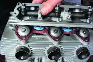
 Picture 16: After that little lot fitting the cylinder head is refreshingly simple. With all dowels and sleeve nuts present and correct the head drops on to its new gasket. Note the lower pushrod tube seals, which I’ve already smeared with silicone sealant and positioned on each tappet block.
Picture17: With the pushrod tubes in place, the next step is to engage the pushrods with the cam followers. A blob of grease on the end of each pushrod makes it easy to fit into the cup on the top of each follower and should hold it in place for the next step. I’ve fitted new rubber seals to the top of each pushrod tube with a fairly generous smear of silicone sealant, and positioned new rocker box gaskets. The exhaust rocker box can then be lowered into place.
Picture 18: I’ve also popped a blob of grease into the top of each pushrod and as I lower the rocker box I can carefully engage the end of each rocker arm with its respective pushrod. To make the job easier (or indeed possible at all) Triumph have provided two screw-on inspection caps on each rocker box casting; with these caps removed a small screwdriver can be used to make certain the rockers are correctly engaged. The long cylinder head bolts now fit through the rocker box into the sleeve nuts atop the cylinder barrel.
Picture 19: The inlet rocker box goes on in the same way and I gently turn the engine over to make sure all the valves open and close correctly before proceeding. The long cylinder head bolts can then be torqued down in diagonal sequence to 18 lb./ft, and the smaller corner bolts and Allen screws fitted to seal the rocker boxes to the head. With everything sealed, seated and torqued down I can now set the valve clearances to 0.006” inlet and 0.008” exhaust, though these will need rechecking after the engine has started and run for the first time.
Picture 20: To “close off” the crankcase I now turn the engine upside down and fit the lower crankcase filter with two new gaskets fitted, sandwiching the filter gauze between crankcase and sump plate.
 Picture 21: While the engine is upside down this is as good a time as any to fit a new oil filter, which simply slides into the crankcase. A spring between the filter and cap keeps it in place, and a new O- ring on the filter cap will prevent it leaking later.
Picture 22: Next, the oil pressure release valve. This bolts into the crankcase and is designed to allow oil to flow past its plunger should engine oil pressure exceed 90 lb./sq.in. Unscrewing the cap from the valve body reveals the spring and plunger, which should be able to move freely in the valve body.
Picture 23: The release valve spring should have a free length of 1 3/8”. With everything cleaned up and working smoothly the cap screws back on with a new O-ring, and the whole release valve screws into the lower side of the drive side crankcase below the oil pump housing. A new fibre washer seals the release valve against the crankcase.
Picture 24: The oil pump is a rotary design with two sets of gears, one side to feed oil into the dry sump engine, and one set to scavenge it back to the oil tank. It’s a self contained unit machined from steel and with two retaining screws removed the pump body can be split to examine the gears. These pumps are robust units and rarely give any trouble, especially as they spend all their working lives immersed in oil.
Picture 25: The final part of the lubrication system is this spring loaded ball valve, designed to stop oil draining back into the crankcase and “wet sumping”. I’ve used a blob of grease to hold the ball in place on the spring while I offer it up to its mounting in the crankcase and tighten it home. ![]()
Advert
 Enjoy more Classic Motorcycle Mechanics reading in the monthly magazine. Click here to subscribe.