
We left off last month in a bit of a quandary after discovering how much it would cost to re-bore Steve’s Kawasaki Z400 twin engine and fit genuine new pistons. Apparently aftermarket piston kits are not readily available for this model and the price of new parts would far exceed the cost of simply replacing the entire engine.
So it was that Steve went in search of secondhand barrels and pistons with rather mixed results…
Enjoy more Classic Motorcycle Mechanics reading in the monthly magazine.
Click here to subscribe & save.
Picture one: While the search for serviceable pistons continues I’ve made a start by beginning to rebuild the bottom half of the engine. With new big-end shells fitted to the rods and the journals copiously oiled I can re-assemble the big ends. I’ve added a spot of threadlock to the big end bolts before carefully torqueing up the bolts. It’s not essential to re-fit the rods on their original journals and the same way round, but it’s good workshop practice and I’ve been most careful to make sure everything is re-fitted in its original place.
 Picture two: I’m also replacing the main bearing shells, so I’ve pressed them into place in the top crankcase half and oiled them with fresh engine oil before carefully lowering the crankshaft into position. The new camchain is also in position on the crankshaft. Incidentally, if only replacing the camchain on one of these engines it is possible to remove the camshaft, then turn the engine over, remove the bottom crankcase half and split the big end caps. This lets you lift out the crankshaft without disturbing the head, barrels and pistons.
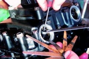
Picture three: The centre main bearing shells fit into the balancer assembly, which needs to be fitted before the crankcase can be re-joined. As the balancer is lowered into position its drive chain engages with the crank sprocket and the balance weights must be timed correctly at this stage. To make sure I’ve got it right I’ve temporarily fitted the clutch case and auto-advance unit, which allows me to line up the ‘T’ timing mark for top dead centre. The two alignment marks on the bobweights (here picked out in white paint) should now line up to their index marks. These don’t look quite right to me and refuse to line up accurately. A quick call to Phil at Z-Power confirms that they are in fact correctly aligned, and the rebuild can proceed.
Picture four: Next, the two gearbox shafts can be fitted into place, making sure the selector forks engage correctly into the grooves on the matching gears. The gearbox bearings all locate onto circlips or dowels in the top crankcase half and I’ve fitted the new clutch pushrod seal. Finally, with everything correctly located and a thin smear of Hylomar applied around the jointing surface, I can lower the crankcase into position and bolt it up, pausing to make sure all the shafts rotate easily before final tightening.
Picture five: This is a convenient time to fit a new oil filter. I’m also re-fitting this gauze strainer into its housing before re-fitting the cover plate with a new gasket. The gauze strainer prevents foreign bodies getting into the oil pump and will be checked and cleaned at the first oil change after the rebuilt engine is run. Any bits of surplus gasket cement will collect here and must not be left to clog the gauze and restrict the oil flow.
 Picture six: Now to the primary drive side. First I’ve slotted the kickstarter assembly home and used a pair of long nosed Mole grips to tension up the return spring and hook it into place. Next, the oil pump sits on its new gasket and is retained by three cross-head screws. I always give these screws a sharp tap with an impact driver to make sure they’re tight and I’ve primed the pump with fresh engine oil before fitting.
Picture seven: With a new oil seal carefully pressed in to the other side of the crankcase I’ve greased the gearchange shaft before sliding it through the crankcase until I can engage the selector claws with the end of the selector drum. The shaft is held in position with a small catch plate fixed to the crankcase with two screws. The selector claws have a small retaining spring and a hairpin centering spring – these need to be engaged correctly as the claws are engaged.
Picture eight: Because the little Kawasaki uses an endless primary chain, the clutch basket and primary drive gear must be replaced together. A washer and spacer fit over the gearbox input shaft first, then the whole primary drive assembly can be offered up and slid into place over the respective shafts.
Picture nine: Now the clutch inner drum fits on to the splined end of the input shaft. Unusually, Kawasaki’s designers chose to retain both the primary drive gear and the clutch with circlips, which makes life much easier provided you own a decent set of circlip pliers.
 Picture 10: Assembling the clutch is simply a matter of popping the clutch plates in, starting with a friction plate and alternating with plain plates until all are in place. The clutch pushrod slides into the centre of the input shaft, followed by a ball bearing and then the clutch lifter mushroom. A blob of Copper Slip on the lifter mushroom will prevent the ‘clutch shriek’ common to many Kawasakis of the period. With the pressure plate fitted the springs can then be tightened down until they stop. Don’t over-tighten these, as it is possible to strip the threads out of the inner drum.
Picture 11: I always grease new gaskets for this kind of application. The gasket should be capable of providing an excellent seal provided the surfaces are not damaged and grease will permit the cover to be removed at a later date without the gasket splitting. With the clutch cover re-fitted I can turn my attention to the ignition components. First the auto-advance unit pushes into place on the crank end and is retained with a single, central 8mm bolt. The unit is keyed to the crank with a tiny dowel, and will only fit in one place. Then I can fit the points backplate. I carefully punched some alignment marks before stripping the engine, so I can now refit the backplate in its original place. This should give me accurate enough ignition timing for an initial start-up, and I’ll check it with a strobe later.
Picture 12: With the clutch side complete I can now move to the engine’s left side. First the starter motor engages down into the crankcase and is bolted up with two M6 bolts.
Picture 13: Then I can replace the generator rotor and starter clutch assembly. Again, there’s an endless chain which connects the starter drive gear to a sprocket on the end of the starter. The starter sprocket simply slides home as the generator rotor fits onto its taper. Finally a single left-hand thread bolt secures the rotor to the end of the crank. I’ve used a spot of blue Loctite to retain it, and torqued it up tight. Then the generator cover complete with stator goes on, and the engine’s sides are more or less complete.
 Picture 14: While I’ve been busy with this lot, Steve has managed to turn up trumps with a serviceable set of second-hand barrels and pistons. Unfortunately the rings that came with them were beyond further use, so Steve has invested almost £70 in a new set of standard rings. Who said parts for this engine would be cheap? After cleaning up the piston crowns I’m fitting the new rings with some care. The top ring is chrome and can go in either way up, but the second ring is cast iron and must go the right way up. A tiny letter ‘N’ alongside the ring gap identifies the top side.
Picture 15: Fitting the pistons is easy enough, though a delicate touch is required to engage the new circlips. I’ve copiously oiled the small ends with clean, fresh engine oil before sliding the gudgeon pins home and used long nosed pliers to pop the clips in. Always make certain the circlips are properly seated before moving on – a circlip which comes loose in service will cause catastrophic damage to the cylinder bore when the engine is run.
Picture 16: Before fitting the barrels I’ve fitted the front camchain slipper blade. Don’t miss it out as you can’t fit it with the barrels on. I’ve also tied up the camchain with a piece of electrical wire which permits me to thread it upwards through the camchain tunnel as the barrels go down. Then, with a new cylinder base gasket greased and in place, and the pistons well oiled, I can slowly lower the barrels, gently easing each piston ring into place with a small screwdriver until all are safely engaged. The barrel should then gently tap downwards onto the crankcase mouth with a rubber mallet.
Picture 17: Next a new head gasket and the cylinder head can be placed on top of the barrels and torqued down. Some engines have small rubber ‘O’ rings around some of the head studs to seal the camshaft oil feed, but as this engine uses an external feed there are no O-rings to worry about. Each head nut has a copper washer to prevent oil draining down the studs from the head and leaking. Make sure the two locating dowels are in place at either side of the head before fitting, too.
 Picture 18: To fit the camshaft I’ve removed its sprocket, then hooked it into the camchain. The camshaft drops into its freshly oiled bearings and I can feed the chain around the sprocket teeth. The trick is then to time the top sprocket to the crankshaft, which again needs to be positioned at the T mark for top dead centre. There’s enough slack in the chain to feed the links over until the timing marks are correct.
Picture 19: With the cam sprocket sitting on its mounting flange the timing mark, here picked out with silver paint, should align with the head flange. It’s then a simple matter to rotate the camshaft until the sprocket bolt holes line up and then fit the two retaining screws, again using a spot of threadlock. And if you were worrying about getting the timing 180 degrees out, forget it. The Z400’s wasted spark ignition system means both cylinders fire together, on both compression and exhaust strokes.
Picture 20: Now, the camchain tensioner. This is a manual tensioner comprising a spring-loaded plunger in an adjustable housing. With the housing screwed into the cylinder barrel until the end of the plunger is flush with the end of the housing, chain tension should be correct. And because the Z400 engine runs ‘backwards’, the tensioner is found at the front of the cylinder barrel, not at the rear. With the tensioner correctly set, a large alloy cap screws over the top to seal it against the block.
Picture 21: This is as good a time as any to check the valve clearances. Because this engine has had significant work done to the valves and seats, it is almost inevitable that the clearances will settle down once the engine runs, so for the time being I’m setting all the clearances to six thou. They will need to be checked soon after the initial start-up and again after the first 500 miles.
 Picture 22: Last item on the top end is this external oil feed pipe for the camshaft. The oil pressure switch fits into the lower banjo and screws into the crankcase, while an upper banjo bolt secures it to the head. Make sure the copper washers are present and in good order.
Picture 23: The engine sprocket cover carries the clutch lifter assembly, so before fitting the cover I’ve removed the lifter to clean and re-grease it. The lifter comprises two ramps with sloping depressions and a centre bearing plate carrying three ball bearings. As one side of the ramp is rotated by the clutch cable, the balls ride up the ramps and push the clutch pushrod to lift the clutch. The Kawasaki lifter is a tough design and shows little signs of wear. After greasing it I can rebuild it into the sprocket cover and fit the cover to the engine.
Picture 24: With the cover fitted, the clutch lifter is adjusted by winding it in until it meets the end of the pushrod, then backing off half a turn and locking with the locknut. A small rectangular alloy cover then bolts on to conceal it.
Picture 25: The finished engine ready to install in its new home. Steve managed to find a good second-hand kickstart lever and a superb stainless screw kit from Inox Fasteners finishes off the detailing. The ever-helpful John Kemp at Inox has gone to great trouble to supply top quality fasteners for what turned out to be a rather obscure engine and I’ve been impressed by the quality of the fasteners and the prompt service and personal interest they’ve taken in the project. The plan is to use the engine to power a mono-wheel such as those we built in TVs ‘Scrapheap Challenge’. With a little more time to design and plan the project it promises to be interesting and I’m looking forward to seeing, and maybe even riding, Steve’s finished machine.
Thanks to Z-Power for gaskets, parts and invaluable advice and Inox Fasteners for whom even the smallest washer is a goal worthy of pursuit. ![]()
Advert
 Enjoy more Classic Motorcycle Mechanics reading in the monthly magazine. Click here to subscribe.