
There are a hundred and one ways to compromise a motorcycle’s performance but one of the most pernicious has to be timing. Getting that all important spark to arrive at precisely the correct moment has a dramatic impact upon the bike’s power delivery. If you check out a manual for your bike you will often see a figure quoted such as 1.4mm +/- 0.05mm BTDC. This means the plug has to fire 1.4mm before the piston reaches the top of its stroke and our degree of variance from that figure is just 0.05 of a millimetre.
There are various methods for getting the spark to the plug but this month we look at one of the most basic and reliable systems, the flywheel magneto. The Japanese took this method of ignition to their hearts because it is so simple, elegant and robust. It can be mass produced at minimal cost and takes very little in the way of clever equipment to set it up with a surprising degree of accuracy.
Enjoy more Classic Motorcycle Mechanics reading in the monthly magazine.
Click here to subscribe & save.
Its only real limitation is the rotating part’s mass. While perfectly OK on a small engine operating at low to moderate revs the iron magnets within the rotor’s body may play merry hell with the crank, its seals and bearing if taken to high speeds. Large rotating masses on the ends of crankshafts are never a good idea.
For this reason the flywheel magneto is normally confined to smaller engines and normally twins. Honda C50s, Kawasaki and Yamaha trail bikes, Suzuki AP50s and Yamaha Fizzies all use the same basic system.
The first thing we need to do to check the timing on a flywheel magneto is to remove the cover or covers that surround the flywheel. Some bikes have a cast outer engine cover along with a pressed steel inspection panel and manuals often show just the latter removed. To make life easier and give unfettered access it’s better to take the entire cover off. Use an impact driver for any stiff or rusted case screws as this will generally give a positive result whereas a worn out Phillips driver is likely to further butcher the screw head causing more hassle.
The spark plug is also removed so that we don’t have to fight with the piston’s resistance to compression. Well here we are (Picture 1) with the cover off. There are four holes in the flat face of the magneto; two large holes for access and two smaller holes that will allow us to grip or hold the flywheel should we need to. To set the timing correctly we need to locate the static timing mark which is normally fixed inside the flywheel on a peg or pointer that’s part of the condenser (Picture 2). Therefore it’s imperative that we have either a genuine condenser or a pattern item of known quality with the same peg.
 Making sure everything is clean and accessible, the main connector from the magneto is unplugged and connected to a battery (6v in this case). We’re using a 6v 21W indicator bulb in an old automotive holder on this job but realistically anything which safely holds the test light away from an earth and is bright enough to see will be fine. With the battery earthed to the engine case via a crocodile clip or similar, the other end of our test circuit is attached to the flywheel magneto's live side. This is normally a black wire or a black wire with a coloured tracer. Here (Picture 3) we’ve got everything connected and a bright bulb confirms the points are open.
On this engine and many others there are two marks etched onto the rotor; one indicates where the points open and the other indicates where the points close. These are our two datum or reference marks and the latter is the key area for our purposes. A workshop manual will highlight what’s what and where’s where, but with our simple test lamp and battery arrangement it should be obvious which mark is which; if it isn’t you either have the wrong points installed or some very serious wear.
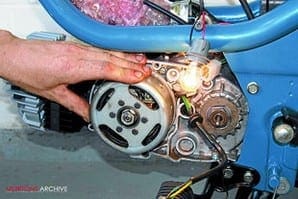
So, moving on to the job in hand, if everything is working as it should and the engine has stopped with points open (as is most likely) your light bulb should be as per (Picture 3). Now turn the engine over in the normal direction of rotation and observe the intensity of the bulb. In theory it should go out but in practice never quite does. As the flywheel rotates and the points begin to close the degree of illumination declines (Pictures 4-5-6). Looking close up we can see here (Picture 7) that the pointer on the condenser lines up fairly closely with the mark on the flywheel.
The perspective of the camera actually indicates a small discrepancy with the flywheel mark slightly behind the pointer but viewed head on they are spot on. It’s worth running through this scenario a few times just to ensure the bulb is at its dimmest and that you are comfortable with the process. Carrying out this procedure in daylight can be difficult particularly with a low capacity 6v battery; either put something up against the shed window to block out the light or pull the garage door down. Kneeling on the drive with a blanket over your head and the bike will result in some very funny looks from the neighbours!
If the timing marks line up the job’s done so reconnect the loom, put the tools away and make a brew; if not we have to get into the bowels of the ignition. There are two methodologies of getting the timing correct dependant on the way the engine is designed but both address the same issue ie wear of the points' faces and abrasion of the fibre heel that bears on the cam mounted inside the flywheel. Process number one, as in our example, allows us to access the points inside flywheel (Picture 8), the adjuster locking screw that holds the points on their back plate and the adjuster slot via the large window in the face of flywheel.
By slackening off the screw and either opening or closing the points gap the timing will be either advanced or retarded. By making a note of the gap and the position of the points closed mark relative to the pointer you will quickly see which way to adjust the gap; greater or smaller. Most workshop manuals will give a maximum gap, anything bigger normally indicates that the points are beyond their service limit and should therefore be changed. Given the low cost, it’s often worth grabbing a spare set at an autojumble or bike show for such eventualities.
Process number two is used when the points are essentially non-adjustable. Here we have to move the back plate or stator around the crank, its keyway and thereby the cam itself. Although a royal pain the process is effectively the same but requires the removal of the magneto, adjustment of the back plate via the stator’s mounting screws and its slotted back plate.
 To remove a flywheel magneto from its taper and keyway on the crank you will need the appropriate puller… period! The fact that your mate’s brother can remove these devices with a spanner, two tyre levers, a crowbar and hammer does not mean you should follow his lead. A flywheel magneto may have been cheap for the Japanese to install in 1974 but a replacement one is going to cost now so spend £7-15 on a puller and not three figures on a new magneto.
Here (Picture 9) we have a typical puller that will provide years of home workshop service without breaking the bank. Genuine factory pullers turn up at shows for sale and some are still available from dealers but unless you are rebuilding bikes for a living a generic version will be fine. Before cracking off the flywheel the centre nut needs to be removed and there are various options here to hold it solid while the nut is loosened. Canvas or rubber oil filter wrenches can be secured around the body or you can even use a chain wrench but the surface is best protected with several layers of duct tape. Workshop manuals often detail a special forked tool with a long holding arm that fits snugly into the two smaller apertures of the magneto and these are very effective at locking the magneto.
On our demo unit I’ve used my windy gun or air wrench; the high frequency percussive impacts imparted to the nut mean there’s no need to hold the flywheel and everything comes apart in a gentlemanly manner.
With the nut removed the puller is wound into the internal thread remembering this is normally a left-handed thread. With everything in place (Picture 10) tighten the puller into the body of the flywheel magneto via the two flats on the puller body and then tighten the bolt. This will bear down on the end of the crank and pull the female taper off the end of the crank. If the unit proves to be reluctant to move, apply just a little more torque and then hit the end of the bolt with a good sharp crack with a large hammer. This axial shock is pretty much guaranteed to loosen all but the most abused or rusted unit.
 Inside (Picture 11) we can plainly see the lighting and HT coils left and right, the condenser and integral pointer at the bottom and the points directly above the crank. Just above the condenser and directly below the crank is the lubricator; this is a little felt pad that retains a film of oil and lubricates the cam and prevents premature wear of the points cam. The points cam is integral with the inside of the flywheel and normally requires no attention unless obviously rusted or damaged.
Sitting at 9 o’clock on the crank is the half moon key that locates the flywheel precisely to the crank taper; lose this and the engine will never run properly. Ideally remove the half moon key and pop it into one of those very useful magnetic trays; it’s so much harder to lose a tray full of parts than one or two vital bits. On the perimeter of the stator plate at 1 o’clock and 7 o’clock are a pair of countersunk crosshead screws and these hold the plate to the crankcase.
In our example this back plate has no adjustment but if you need to remove the stator or alter the timing via slotted mounts a quick crack with an impact driver should see the screws loosened. If these screws are damaged do not be tempted to replace them with Allen bolts or hexagonal headed fittings. The screw heads need to lie below the surface of the plate otherwise they can potentially rub against the magnets or pole pieces within the flywheel causing serious damage.
While we’re in here it’s worth checking that the wiring is properly routed and free from damage. The coil's mounting should be free from cracks and should be firmly mounted with no rock or movement. Have a good look at the quality of the insulation of the coil's windings. The odd crack or missing flake is probably just about acceptable but having two adjacent wires without insulation touching is asking for trouble. Either replace or seek expert advice on whether it’s possible to get them rewound. Although Japanese wiring insulation is infinitely better than the shellac coated rubbish from Wipac or Joe Lucas it is likely to be a quarter of a century old and not in its first flush of youth.
Also check the lubricator pad has some oil. Here (Picture 12) we’re adding a few drops of sewing machine oil; not enough to run off the felt pad but sufficient to ensure the cam and points heel don’t wear unduly. Finally, have a quick look at the crankshaft oil seal; if it’s leaking you’ll see oil around the stator and possibly a little weep running downwards. With care these seals can be changed in situ.
With everything set up and checked the flywheel is carefully replaced on the taper ensuring the half moon key is in place, the nut and any washer fitted and retightened. There should never be any need to add any form of engineering adhesive to the taper and if it is used it may make it impossible to later remove the magneto from the crank.
Old fashioned engineers will probably add a dab of saliva to the taper for good measure; this promotes a controlled level of corrosion within the taper and ensures a pretty much perfect joint. Check the motor runs OK, replace the engine covers and enjoy the inherent reliability of a very effective ignition system that doesn’t need the complications of a single silicon chip. ![]()
Advert
 Enjoy more Classic Motorcycle Mechanics reading in the monthly magazine. Click here to subscribe.